Authors: Martin Bredberg & Thomas Pfeiffer
General guidelines
Injection molded plastic parts should be designed to get the best results
Uniform thickness
Injection molded plastic parts should have walls with proper and uniform thicknesses. Walls should neither be too thin to avoid problems to fill them with plastic nor too thick to have problems with cavities (air bubbles).
Uniform wall thicknesses mitigate problems with different shrinking during cooling. Tolerances can be kept better. Transitions from thin to thicker walls should be smooth or rounded.
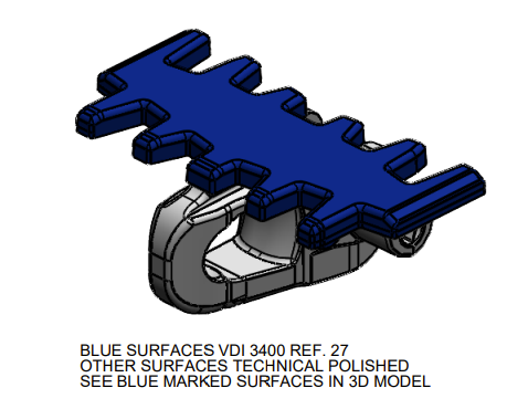
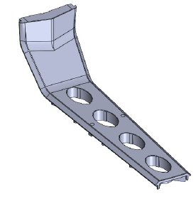
Surface roughness
Surfaces should be defined in the drawings. E.g. chain links should have defined VDI surfaces for visible surfaces of the part and technically polished surfaces for the base under the top plate which are in contact with the slide rail.
Example (X65 link)
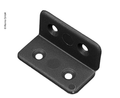
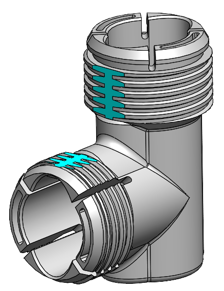
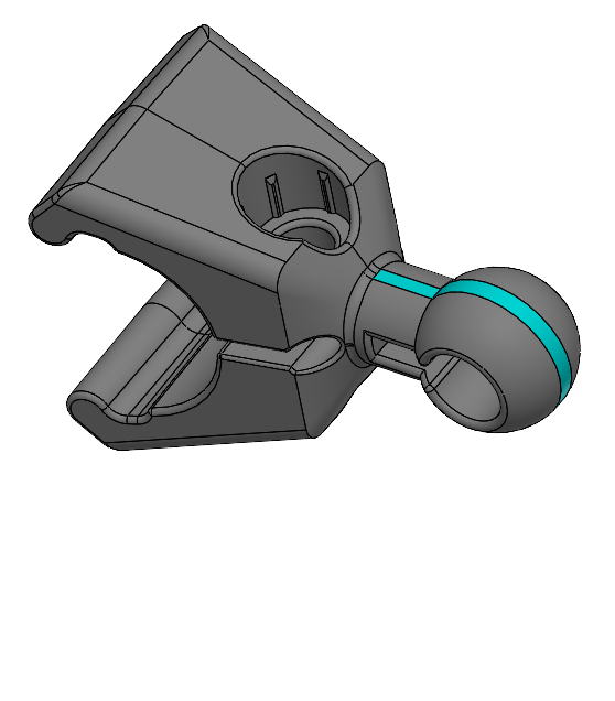
Snap function
When you design a snap function for an injection molded plastic part consider the demolding of the part. Demoulding could be done by forced demolding, lifters (sliders in an angle moved during opening the tool) or seperate sliders with pneumatic cylinders.
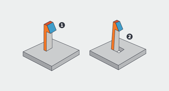
Example for forced demolding - the part popps out of the tool
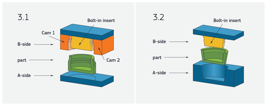
Lifters - moved by opening the tool

Complicated demolding can be avoided by opening up the part under the smap-fit hook. Please check if it could be possible
We have various materials for our 3D printers. Try to find one which has similer properties like the material for the final part and test it before you order the tool.
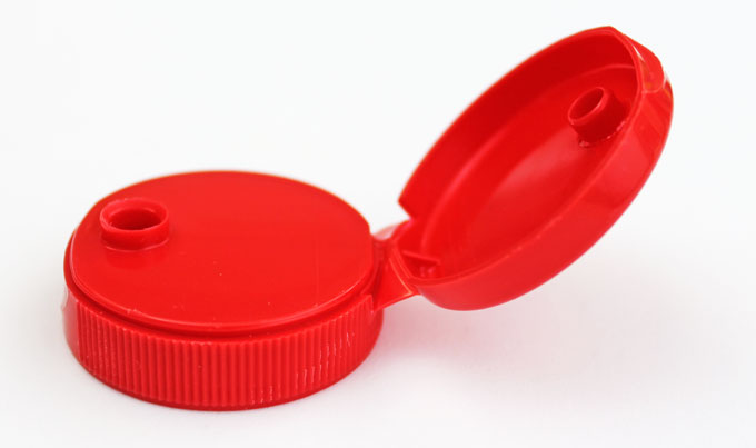
Hinges
You can make a hinge in an injection moulded parts as a film hinge. It's a thin and flexible wall connecting the two parts of the hinge.
For film hinges choose soft and flexible plastic materials as PP or PE. Brittle materials like PC will not work properly.
FlexLink does not have any or maybe a very few parts only with film hinges. It's recommended to contact the supplier to find a proper design and thickness for a reliable and long lasting film hinge.
Examples for parts with a film hinge
Inserts and clocks
For change of part number, material etc
Common problems/issues
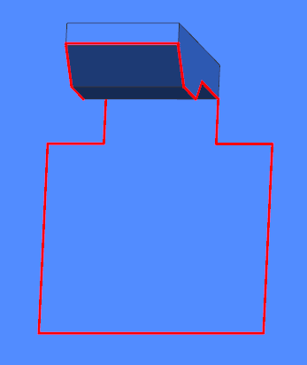
Warping
If you expect warping, try to avoid it by making changes to the
design or material. Warping (curved) sides may be minimized by making a
groove at the bottom of the wall, causing the material to freeze in the
corner, helping to keep the walls straighter. 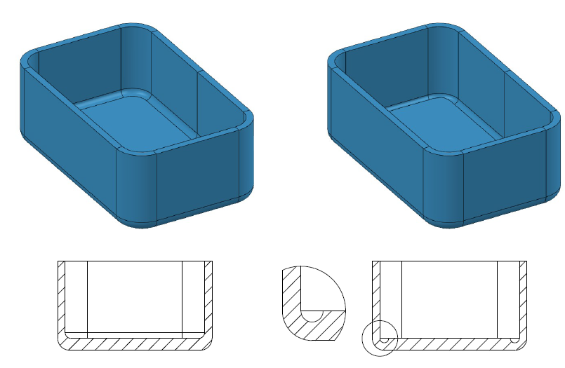
Figure 1 A groove at the corner causes the material to freeze and lessens the risk of warping.
Sink marks
Avoid sink marks by having a uniform wall thickness. If you cannot avoid sink marks, it may be better to add some feature that hides them (they will appear where the goods is thicker than the surrounding). A small dot on the trouble side will at least look intentional.
Sink marks that cannot be avoided can be replaced by "decoration". Not ideal, but better than randomly sized sink marks.
Weld line
A weld line typically occurs when two fronts of the melted plastic meet after passing a hole - it cannot be avoided. The weld line decreases the strength of the area, and may also be visible, making the part look bad. In order to make the weld line as strong as possible, it is important to ensure the pressure on the plastic remains high under the cooling phase. To ensure this it is vital to NOT have any sections of thinner wall/goods thickness between the injection gate and the weld line, and also consider where to place the injection gate.

Split line
Where the tool opens there will be a small split line on the part, a normally very small ridge of excessive material - called flash - that is pressed out between the halves (or cores, inserts etc.) of the tool. Normally this is less than 0.05 mm, but it normally increases as the tool wears.
If the area of the split line is to be used for very tight fits, take some action to ensure the flash does not hinder the intended function - for instance remove some material.
Interaction with part supplier / toolmaker
Please contact the supplier of the injection molded part early enough in the design process to get input how to design it to get the best result.
These things should be considered as well:
Drafts
Gate positions
Parting line
Ejector pins
Best plastic material chosen